 As I mentioned during the last Blue Pints episode, this year I’m going to be attempting to build a low-cost open source CTD for basic oceanographic measurements. This is in addition to my ongoing work with the OpenROV. I have a pretty solid electronics background, but in order to accomplish this goal, I also need to learn how to program microcontrollers, something that I’ve never done before. For the next several months I’m going to tackle various small Arduino project to get comfortable with the fundamentals. I’ll be working out of Environmental Monitoring with Arduino: Building Simple Devices to Collect Data About the World Around Us and Arduino Projects to Save the World, both of which feature beginner to advanced projects based around environmental monitoring and data collection, as well as Programming Arduino Getting Started with Sketches for as a basic programming primer.
For my first project, I wanted to start with something that could eventually be implemented with the OpenROV–a magnetometer to provide compass headings while navigating the robot. As a first step, I wanted to learn how to program the Arduino board to calculate compass headings from a magnetometer and develop some sort of rough visual readout of that heading.
Parts
- Arduino Uno
- 3-axis Compass Module
- Large breadboard
- Small breadboard
- 1 red LED
- 3 green LED’s
- 4 220-ohm resistors
- jump wires
Step 1: Connecting the compass module to the Arduino analog outputs.
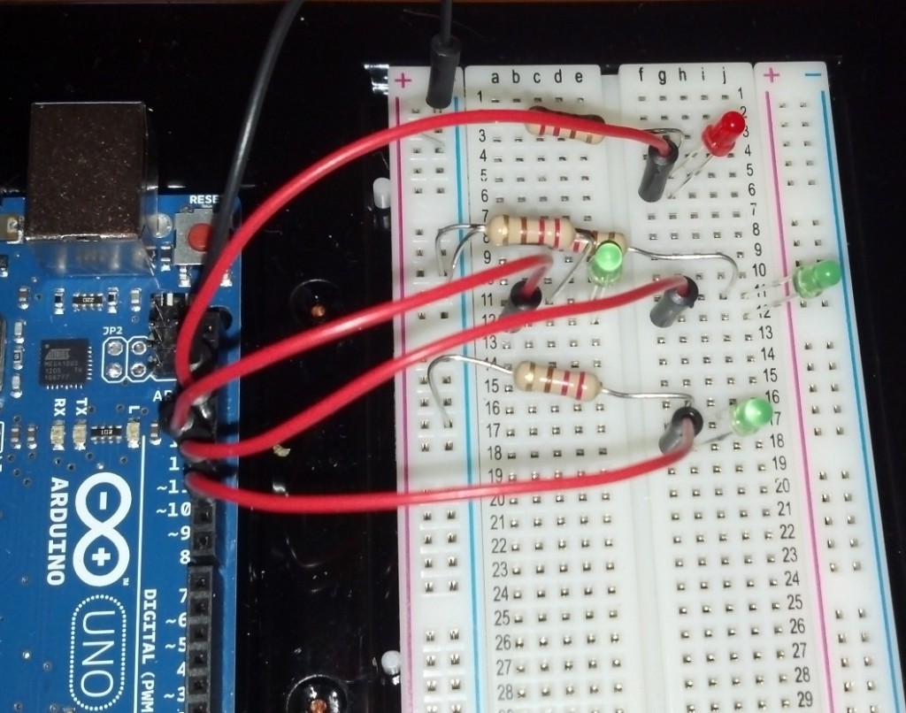
I mounted the compass module to a small breadboard so that I could move it around independent of the rest of the setup. The pin labeled VIN connects to the 5V output on the Arduino, SCL connects to analog ouput A5 while SDA connects to A4. Ground connects to ground.

Step 2: Connecting the LED array to the Arduino digital outputs.
I arranged the 4 LED’s in a diamond shape, with the red LED indicating North. Connect the ground from the Arduino board to the negative bar of the breadboard. Each 220-ohm resistor connects the negative bar to the negative lead of the LED. If you’re following my program, pin 13 connects to the North LED, 12 connects to West, 11 connects to East, and 10 connects to South.
That’s all the set up you need to do.
Step 3: Programming.
I used the open source example program provided with the compass module as a template to add the LED commands (and removed some extraneous data being sent to the serial monitor. For the LED lights, I just added a series of 4 “If ” loops to turn the lights on or off depending on which way the compass is pointing (note the the X-axis on the 3-axis compass module corresponds to your bearing). I also had to adjust for my declination angle (the difference between compass north and true north). This varies depending on where you are in the world and should be inserted into the code in radians.
Final Thoughts
This was my first project beyond the basic “make an LED blink” tutorials. It was simple enough that I could tackle it with some basic programming knowledge but complex enough that I had to spend some time figuring out how to get the program right. I also produced a “cool thing” that will eventually lead to something practical for my larger projects.
Full Arduino Code reproduced below:
#include <Wire.h>
#include <HMC5883L.h>HMC5883L compass;
int error = 0;void setup()
{
Serial.begin(9600);Serial.println(“Starting the I2C interface.”);
Wire.begin();Serial.println(“Constructing new HMC5883L”);
compass = HMC5883L();Serial.println(“Setting scale to +/- 1.3 Ga”);
error = compass.SetScale(1.3); // Set the scale of the compass.
if(error != 0) // If there is an error, print it out.
Serial.println(compass.GetErrorText(error));Serial.println(“Setting measurement mode to continous.”);
error = compass.SetMeasurementMode(Measurement_Continuous); // Set the measurement mode to Continuous
if(error != 0) // If there is an error, print it out.
Serial.println(compass.GetErrorText(error));pinMode(13, OUTPUT);
pinMode(12, OUTPUT);
pinMode(11, OUTPUT);
pinMode(10, OUTPUT);
}void loop()
{
// Retrive the raw values from the compass (not scaled).
MagnetometerRaw raw = compass.ReadRawAxis();
// Retrived the scaled values from the compass (scaled to the configured scale).
MagnetometerScaled scaled = compass.ReadScaledAxis();// Values are accessed like so:
int MilliGauss_OnThe_XAxis = scaled.XAxis;// (or YAxis, or ZAxis)// Calculate heading when the magnetometer is level, then correct for signs of axis.
float heading = atan2(scaled.YAxis, scaled.XAxis);// Once you have your heading, you must then add your ‘Declination Angle’, which is the ‘Error’ of the magnetic field in your location.
// Find yours here: http://www.magnetic-declination.com/
float declinationAngle = -0.1742;
heading += declinationAngle;// Correct for when signs are reversed.
if(heading < 0)
heading += 2*PI;// Check for wrap due to addition of declination.
if(heading > 2*PI)
heading -= 2*PI;// Convert radians to degrees for readability.
float headingDegrees = heading * 180/M_PI;//Light North LED
if(headingDegrees > 325 or headingDegrees < 45)
{
digitalWrite(13, HIGH);
digitalWrite(12, LOW);
digitalWrite(11, LOW);
digitalWrite(10, LOW);
}//Light South LED
if(headingDegrees > 135 and headingDegrees < 225)
{
digitalWrite(13, LOW);
digitalWrite(12, LOW);
digitalWrite(11, LOW);
digitalWrite(10, HIGH);
}//Light West LED
if(headingDegrees > 225 and headingDegrees < 325)
{
digitalWrite(13, LOW);
digitalWrite(12, HIGH);
digitalWrite(11, LOW);
digitalWrite(10, LOW);
}//Light East LED
if (headingDegrees > 45 and headingDegrees < 135)
{
digitalWrite(13, LOW);
digitalWrite(12, LOW);
digitalWrite(11, HIGH);
digitalWrite(10, LOW);
}Output(raw, scaled, heading, headingDegrees);
}void Output(MagnetometerRaw raw, MagnetometerScaled scaled, float heading, float headingDegrees)
{
Serial.print(headingDegrees);
Serial.println(” Degrees \t”);
}
Hey Andrew,
I’m a postdoc in physical oceanography at WHOI, and have recently gotten interested in arduinos and building oceanographic and meteorological sensors. Mostly just because I like to build things, and it’s a neat avenue for potential outreach and teaching, but I like your approach of “low cost and open source” for the community.
I’ve been playing around with some simple conductivity sensor designs, and I’d be happy to bounce ideas back and forth. I’ve been thinking I should just start documenting everything in a blog as I go.
Have you seen this paper?
da Rocha, R.T., I.G.R. Gutz, and C.L. do Lago. 1997. A low-cost and high-performance conductivity meter. Journal of Chemical Education 74:572 –574, http://dx.doi.org/ 10.1021/ed074p572.
I have a pdf copy if you can’t get access somewhere. I haven’t tried their design, but it’s a possible starting place or even just a fun test to see how it compares to other DIY and commercial solutions.
Cheers,
Clark Richards
Hi Clark,
Thanks! I too started this up for no other reason than I like to build stuff. I was actually planning on taking a first pass at a conductivity meter this weekend. The probe from that paper looks significantly more robust than the wire-and-foil job I was going to work up. I think with some clever programming, the arduino can handle the current-to-voltage conversion, rectifier, and filter, so that circuit can be much simpler.
Temperature and pressure probes are pretty straightforward, it’s just a matter of building them tough enough to drop in the ocean, so I imagine conductivity will be the major challenge for this project.
Have you seen the OpenTAG and OpenROV projects?
I’d love to to have someone to bounce ideas off of. A blog to document progress can be very helpful (or just let us know how things are going in the comment threads here).